Introduction
Since last five years, our research on external/peripheral “assistive-technologies and personalized” has been described in this neuroscience journal. Mainly deep brain stimulators (DBS) designed for the meant for the patients respite as of from the feature-manifestations, i.e., signs and symptoms of Parkinson disease, have also been published here,1 as well as elsewhere.2, 3
A computational prototype model simulator of PD (Parkinsonian) pathological ‘oscillatory-activity’ as well as its control through the application-of high-frequency-stimuli is given. 2, 3, 4 Its a type of “macroscopic neural-mass model” whose objective was to acquire the “prime-features” of a synchronized “group-of-neurons” by mathematical-frameworks. It`s proved to generate hypothetical findings which offer a fit in near accord through clinical/and or diagnostic information/data issued within, 5, 6
In this study, the prototype-model produced within the2 is employed “as the basis” through which to detect “oscillatory-activity” within oscillating (self) as well as non “self-oscillating” connected-loops. Which is kindled through the reflection that BG (pathological) oscillatory-fluctuations within the range-of 3Hz – 300Hz have had been logged in PD subjects (patients). So, we indicate that the contact among “different-loops” both tuned to the ‘specific-frequency’ and/or fundamentally and intrinsically non-oscillatory might yield to this “range-of oscillatory-frequencies”. So, we investigate this scientific-rationale/hypothesis by employing two ‘inter-connected-loops’ customary to established to (compute) generate oscillatory-fluctuations within the shaking hand-tremor with a frequency-ranges as well as, though even though which can be effortlessly stretched to include, incorporate a widespread frequencies varied for instance seem within the PD BG local field potential recording`s. 7, 8, 9, 10 Systems “control-theory concepts”, especially application of “root-locus” a geometrical mathematical frameworks study evaluation, are employed to investigate, to infer the prototype-model simulator.
Materials and Methods
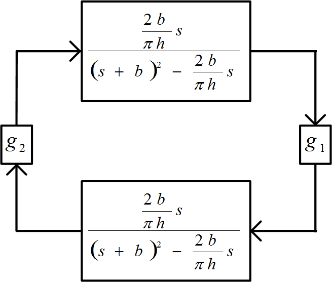
In this study we demonstrate our findings achieved through our experiment’s till now through the computation, we have generated the different range of frequencies which are detected within the basal-ganglion-circuitry as of the inter-connecting of our fundamental basic-building model-simulated prototype depicted in Figure 1. Aimed at the g1=g2>0 we have + / + coupling and for g1=−g2 <0 we have +/− connecting.
Figure 1
Basic building blocks of the fundamental system deemed. ‘+ / +’ combinational connection has had g1=g2 >0, and also ‘+ / -‘connection has g1 =−g2 <0.
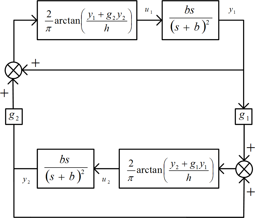
Intended for tiny small-scale signal-analysis methods, the arc tangent nonlinearities are swapped through their tiny signals/waveforms gain`s (voltage gains)
The tiny signals comparable and corresponding circuitry is depicted in the Figure 2, in which we established the “closed-loop” and ‘transfer-functions’ of the two “feedback-loops” that are connected.
The fundamental basic-characteristic multinominal (polynomials) of the tiny-signals signal system is
Our utility—tools for P(s) which is a locus-of-root (i.e., root-locus”) technique 11, 12, is based on the examination that the P(s) is the form of the equation (3)
P(s)= N2(s) – K M2(s)..........(3)
Through
M(s) = s ........... (4)
Now substituting this equation (4) in to the equation (5) yields
In the equation (3) which is indicating as
N(s) = A +jB ..............(6)
M(s) = C + jD
The roots and values of s for that P(s) = 0, is regulated through the following equation (7)
Associating the real-parts as well as imaginary—parts of the equation (7) individually to 0 (stating that “K” is the real and true-parameter) yields the following equation (8) which is the equation of root-locus,
[AD-BC] . [AC + BD] ............. (8)
As of the equation (4), we have, depending on the equation (5)
C =
Decomposing in to two sections (equations 10, and 11)
Plus
The expression (10) merely implies that portion of “root-locus” rests on real-axis coordinates(x and y). The “Evans root-locus” drawing laws is used, which shows that a pure “real-axis”, so the “root-locus” expression is as follows
AD – BC = 0 ................(12)
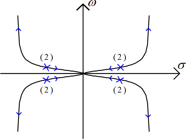
is depicted in figure 3, meant for b=10π, and h=0.3 yields dual poles, i.e., roots-of N 2(s)=0 at
s = 1.9174±j31.3574 ..................(13)
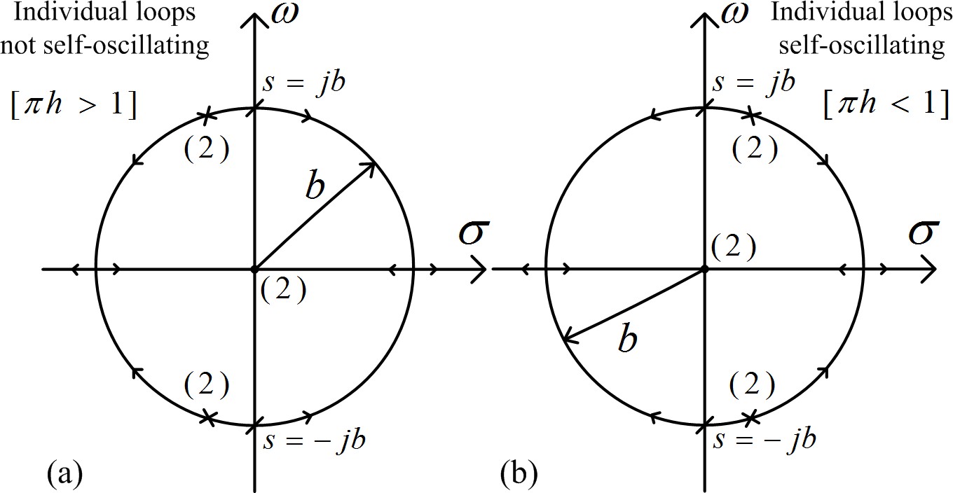
Uncertainty we have had if “πh>1”, then the poles (polar-coordinates) can be within the second and third quadrants, i.e.,”left-half-plane”, nonetheless the circle can be observed towards left-plane as well as to the right-plane as “K is approaching incrementally, plus system can be over the “point-of-oscillation” at the s=jb, as well as fluctuatory-oscillations ahead of, further than, and beyond that, away from it. Therefore, ‘ + / ‘ the locus of root, i.e., the ’root-locus’ is defined through the root-locus characteristic equation
AC+BD = 0 ................(14)
Which yields
The 2-two drawings of the analogous ‘root-locus’ is depicted in the Figure’4. It may be worth here that the for the for
Findings
Initially in the beginning, we underwent on set of fluctuatory-oscillations within the + / + status quo/scenario through “πh>1”, getting “h=0.4” (different loops “un self oscillatory”). The areas/branches immediately begin as of the poles showed within the “left-half-plane” inside the Figure 3, and also understand the “circle” to that of right-half as ‘g’ is approached increasing. The easy and straightforward presentation/function of the “root-locus” ‘calibration-expression’
by the side of one or the other traversing (intersection) point-of “imaginary-part coordinate-axis”, s=jb, yields significant value-of “g1=g2”
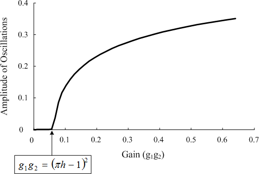
Which is depicted in Figure 5.
Figure 5
Stimulus-amplitudes of oscillations as a “function-of-gain” (“g1g2”) meant for the “value-of h=0.4” (in which the system is not/non un-self-oscillatory”). The curvature is obtained through model-simulation of system depicted in the Figure 1.
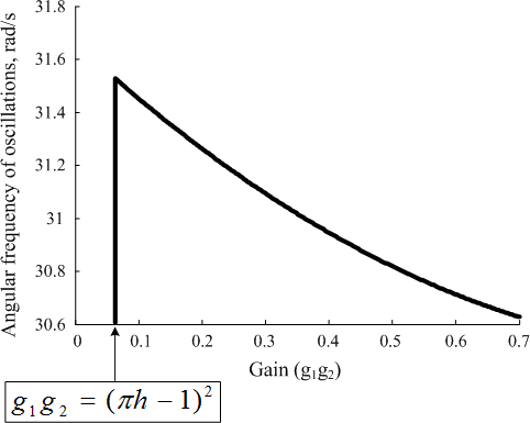
The “angular-frequency” of the ‘oscillations’ of coordinate ‘y1’ as a function of “g1”, defined and then derived through the model-simulator (model-simulating) the system within the Figure 1, as well as through ‘h=0.4”, is shown/marked inside the Figure 6.
Figure 6
“Angular-frequency” of oscillations of “y1” as a “function of the gain” (g1g2) defined and then d e r I v e d by the ‘model-simulating” the system shown inside the Figure 1.
Now let us go to the + / connecting-coupling, instead of that the “root-loci”, within the unequivocal self oscillatory and non/un “self-oscillatory” methods and modes, that are depicted within the Figure 4. So, all “these root-loci” are defined through the following expression
AC+BD= 0 ...............(18)
And approaching and then leadingto
In which,
and then
replacing designed for “ω” as of the equation/expression-19, establishing.
In which “δ” gives the variation from the pole σ coordinates of ζb
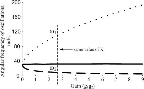
The Figure 7 , analogous to the “right-half of the ‘plane’ the ‘root-locus’ branch-offs within the Figure 4, depicts the advancing approach as well as the reducing the ‘frequencie’s that should be computed/generated with changing/ varied g1=g2 within the + / position. The “geometric-mean” of the those 2-frequencies, observes relatively and easily as
Normal images/figures developing as of connecting shaking palsy-tremor frequency-band-oscillations” are b=10π, ζ=−1
Figure 7
“Angular-frequencies” of beta-oscillation of ‘y1’as a ‘function-of-gain’ (‘g1g2’) defined and thenderived through model- simulating-system showed within the in Figure 1, meant for + / event, by ‘h=0.3’ (‘the system of ‘self oscillatory’). GM of 2two-/frequencies, that remained chronic or continuous, and is added.
Conclusions
This study showed the neurons demonstrating oscillatory fluctuations behavioural-activity at the shaking palsy-tremor-frequency usually 4Hz–6Hz are situated within the abaxial-region/area of nucleus/the sub thalamic nuclei, in which the neuron’s through βac tivity usually 15Hz–30 Hz were examined which advised that the examination of connections of our-“basic-oscillator” which has verified of countless worth in corresponding deep brain stimulation findings may show some knowledge on the diversity-of-frequencies detected within the BG-circuitry of Parkinsonian subjects who are p/t`s-patients. It appears likely that the + / connecting-couplinsg of “neurons” set to shaking-palsy/tremor or else other-frequencies” may compute/generate entire range-of-frequencies” observed in/during “disease-states” associated through “pathological-oscillations” within BG plus other tertiary care hospital research centres.

